SRDT Posted June 1, 2016 Report Share Posted June 1, 2016 The valve cover is made out of Magnesium by STIHL, the bare metal under the paint can look strange if you are expecting aluminium. Quote Link to comment Share on other sites More sharing options...
Goce Posted June 2, 2016 Author Report Share Posted June 2, 2016 19 hours ago, SRDT said: The valve cover is made out of Magnesium by STIHL, the bare metal under the paint can look strange if you are expecting aluminium. I know is written on the valve cover, i want to do something interesting like hydrographics but if there's money in the budget. Quote Link to comment Share on other sites More sharing options...
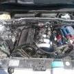
Goce Posted June 2, 2016 Author Report Share Posted June 2, 2016 Today started by pulling the engine and making room for the engine to go back in the cockpit, having the weight of the engine and box over the front axle will make the car understeer like the VW's B5 platform, so i found the center mass of the engine and box and will place it exactly over the front wheels and lower in the frame for lower center of gravity, that all will help me to clear the bonnet and will have larger space for the radiators and intercooler, at first i cut the steel and insulation and test fited the engine needed more space, engine out cut the first plastic from the heater box, again test fit still to tight then i cut it all the way to the heater core and cat back the subframe for the gearbox now fits. Quote Link to comment Share on other sites More sharing options...
Goce Posted June 2, 2016 Author Report Share Posted June 2, 2016 This is close to the right place where the engine will live, it should fit under the center console and look like from the factory, the exhaust manifold will have to be modified is very close to the subframe, not a big deal, may weld the T3 flange now, just to bolt the turbo on when i found a standalone engine management. Quote Link to comment Share on other sites More sharing options...
Goce Posted June 2, 2016 Author Report Share Posted June 2, 2016 I went to the breakers yard yesterday to get a smaller steering rack, got this 3 pumps, couple of high pressure lines, steering rack, i chose this rack because it exits 90 degrees for the steering wheel, in the picture you can see the place where it will live, under the subframe, tie rod ends are very different and will have to make a custom setup to eliminate bump steer, also got two joints for the leakage. Quote Link to comment Share on other sites More sharing options...
Bean Posted June 3, 2016 Report Share Posted June 3, 2016 Just WOW. I read, and then re-read every post... It's an absolute pleasure to be along to watch you through this build process Goce... Carry on... Rabin Quote Link to comment Share on other sites More sharing options...
Goce Posted June 3, 2016 Author Report Share Posted June 3, 2016 Today started by test fitting a distributor cap, i need to cut little more for the wires to pass, next i remove the exhaust collector i'll need to modify it later, interesting the studs for it are stainless steel, after that i started test fixing the steering rack, i need to cut the subframe for the rack to come through, it will be the lowest point on the car, so i have to make some sort of rock gard. Quote Link to comment Share on other sites More sharing options...
Goce Posted June 4, 2016 Author Report Share Posted June 4, 2016 Today i started planning the cooling system, the lower radiator hose flange, had a broken drain bolt, i had a XU5 flange but it has only 2 small hose nipples,thankfully the drain bolt is the same, so i found new o rings for both the flanges, and i plan to use the original one, but i have the other ready if i don't need all the nipples. Quote Link to comment Share on other sites More sharing options...
Goce Posted June 4, 2016 Author Report Share Posted June 4, 2016 i've ordered this lock cylinders, couple of months back and they got lost in delivery, i've forgot about them and today they arrived, they are a copy not oem, but for the price good enough, the driverside one on my mi16 is broken and they are 25 years old. Quote Link to comment Share on other sites More sharing options...
Goce Posted June 4, 2016 Author Report Share Posted June 4, 2016 I need to found or make new dropped tie rod ends, that need to be drop about 3" any suggestions ??? Quote Link to comment Share on other sites More sharing options...
Bean Posted June 4, 2016 Report Share Posted June 4, 2016 Drifters use extended tie rods using spacers and rose/heim joints - do you need an oem solution or can you use something custom? http://www.speedparts.biz/partnum.php?part=22101212 Rabin Quote Link to comment Share on other sites More sharing options...
Goce Posted June 4, 2016 Author Report Share Posted June 4, 2016 I know about heim joints, at 90mm i think it will flex to much, and i need it to look as oem as possible for the safety inspection. Quote Link to comment Share on other sites More sharing options...
andrethx Posted June 5, 2016 Report Share Posted June 5, 2016 goce -- your photo gave me an idea. get the drifter heim joints, cover them in spray adhesive and throw dirt on them --- instant oem look for inspection... Quote Link to comment Share on other sites More sharing options...
Goce Posted June 5, 2016 Author Report Share Posted June 5, 2016 Thank you guys, i'm more concerned for the strength and flex, than the inspection, is nice to see everybody back posting on the forum. Quote Link to comment Share on other sites More sharing options...
Goce Posted June 5, 2016 Author Report Share Posted June 5, 2016 Today got couple more parts, got a clutch line stainless braided, and my fuel filter araved, i plan to run 2 pumps and need 2 filters, the one on the car is new, plus this one, more to come. Quote Link to comment Share on other sites More sharing options...
Bean Posted June 5, 2016 Report Share Posted June 5, 2016 I don't think flex in the drifter style extended tie rods would be a concern, I'd be more worried with bent tie rods... Another option would be to move/change the arm on the spinde so the tie rod could be straight. Rabin Quote Link to comment Share on other sites More sharing options...
Mike T Posted June 6, 2016 Report Share Posted June 6, 2016 It's an impressive project and a massive amount of work. Didn't you like the 4WD chassis? Is it really not possible to get parts for the X4 models any more? I think that setting the car up to drive well once it's all back together will be a lot of work too. Good job. Quote Link to comment Share on other sites More sharing options...
Goce Posted June 6, 2016 Author Report Share Posted June 6, 2016 9 hours ago, Bean said: I don't think flex in the drifter style extended tie rods would be a concern, I'd be more worried with bent tie rods... Another option would be to move/change the arm on the spinde so the tie rod could be straight. Rabin It is hard to show the problem because i have a limited space around the car but in short, i've dropped the steering rack close to 35sm lower in the frame, to have any chance for working i have to re drill the taper in the spindle from the other side, that should drop it about 50mm, and i need 90mm more to get it where it won't hit the subframe, the suspension now is in full dropped, all the drifter drop tie rod ends that i found are 50mm drop i need 90mm and at that length the 12 mm rod in them will flex, i've been on it for the past couple of days, yesterday i spoke with a aircraft engineer and the suggestion he gave me was to found the longest tie rod end, and bend it how i need it, i do not thing that is that easy, but has given me an idea that will work. Quote Link to comment Share on other sites More sharing options...
Goce Posted June 6, 2016 Author Report Share Posted June 6, 2016 4 hours ago, Mike T said: It's an impressive project and a massive amount of work. Didn't you like the 4WD chassis? Is it really not possible to get parts for the X4 models any more? I think that setting the car up to drive well once it's all back together will be a lot of work too. Good job. Thank you Mike i've loved the 4wd until it broke, yes it is that hard to found parts for it and is weak it breaks with factory power, the main thing for me is to make the driveline bulletfroop so i can turbo charge it later with no fear of breaking gearboxes or other parts and won't chew up my tires in a week from lack of traction. Quote Link to comment Share on other sites More sharing options...
Goce Posted June 6, 2016 Author Report Share Posted June 6, 2016 Today started by planting the engine mounts, i had this engine mount that is use for hanging from the frame, but is is too big, the frame is very thin and it has a bend where i need to bolt it, so will not work, after that pulled the engine out for the 38 time now, and cut back the subframe for the rack to fit, wanted to make mounts for it, but i don't have a piece of steel to weld the subframe, and make the steering rack mounts, so i moved to making the steering linkage, and after that cut back the fire wall and floor to make more room for the distributor, tomorrow i need to go to the steel yard to get some more steel and buy couple more cutting discs, more to come. Quote Link to comment Share on other sites More sharing options...
andrethx Posted June 6, 2016 Report Share Posted June 6, 2016 as others have noted, goce, it's exciting to see your work here, all the twists and turns of a project of this type! thanks for posting all of this. a basic question -- the clearance issues that you're working on with the steering, they result from the need to lower the engine because of the fit issues you get from the re-orientation of the engine, correct? Quote Link to comment Share on other sites More sharing options...
Goce Posted June 6, 2016 Author Report Share Posted June 6, 2016 Thank you Andre, you are all welcome, i enjoy communicating with everyone and helping every way i can, i apologise for my grammatics in my posts, my english is self taught. As for the clearance issues are because i've rotate the engine, and the gearbox is massive and it has no provision for a steering rack, the car is from, uses a steering box in front of the engine, i'm very persistent and i will make it work as it should, you may notice every solution is based on making it myself, that is because is the cheapest way, the salary in my country are very low, so i'm sourcing parts as cheap as possible to be able to make it happen. Quote Link to comment Share on other sites More sharing options...
Goce Posted June 7, 2016 Author Report Share Posted June 7, 2016 I've been busy with everyday life but i'm using every spare minute working on the car, today i went to the steel yard and got some flat stock and angle iron, is should be enough to weld a subframe and make a rock gard after i mount the steering rack i need to check if there's enough space for the engine to go in and out i also got this heavy duty crossmember is zinc coated and i plan to use it unmodified i prefer overbuild then underbuild, the pieces may be thicker than necessary, i started on paper template, but got a call and have to stop, also got a thick piece of steel of which i plan to make my custom tie rod ends, little worry for the weight, that piece is 18kg and it neads a lot of machining, more to come. Quote Link to comment Share on other sites More sharing options...
Goce Posted June 9, 2016 Author Report Share Posted June 9, 2016 Today i spend a full day in the garage, first i repair my mig welder to start welding on this project, started by cutting and tack weld the first piece, the second piece need a notch to clear the steering rack lines, then i tack weld it too, then i add one more piece around the rack, after that i removed the A/C radiator, is much bigger than i thought, now i need to close the box with a piece of plastic so it will work i desperately want to keep the heater, it will be tight under the dashboard. Quote Link to comment Share on other sites More sharing options...
Goce Posted June 9, 2016 Author Report Share Posted June 9, 2016 In the evening i was back working on the car, put the engine back in the engine bay and started test fitting the inlet manifold and the battery box, it clears the steering rack and it clears the distributer cap, then the piece of pipe i've order last time i was in the steel yard arrived and i didn't wanted no time cutting it and fitting it is perfect it will box in the front end, i also plan to bolt the cromeber to stiffen the front and have it removable will be out of the way when engine is in and out, then went under the car and install the rear part of the driveshaft, by the look and after measuring the angle i will have to run cv joints, i'm thinking a front axle if i can found strong enough Quote Link to comment Share on other sites More sharing options...

Recommended Posts
Join the conversation
You can post now and register later. If you have an account, sign in now to post with your account.