Goce Posted June 9, 2016 Author Report Share Posted June 9, 2016 Can someone see something wrong with the allen bolts on the outside? Quote Link to comment Share on other sites More sharing options...
SRDT Posted June 9, 2016 Report Share Posted June 9, 2016 Yep pentagon screws, you can see that often on brake calipers. The shaft was balanced as a whole and with those screws you can't unbalance it or at least not by accident. Quote Link to comment Share on other sites More sharing options...
estland Posted June 10, 2016 Report Share Posted June 10, 2016 This might be the first RWD 405 ever made. Keep up the good work! Quote Link to comment Share on other sites More sharing options...
Goce Posted June 10, 2016 Author Report Share Posted June 10, 2016 1 hour ago, estland said: This might be the first RWD 405 ever made. Keep up the good work! There is a RWD Peugeot 405 which is made by Iran Khodro for he Iranian market since 1997 It's based on the underpinnings of the Iran Khodro Paykan, which itself is based on the 1966 Hillman Hunter which was rear drive, but is not performance orented, and is not made in france and just for he Iranian market . Quote Link to comment Share on other sites More sharing options...
Goce Posted June 10, 2016 Author Report Share Posted June 10, 2016 Today i started working on the shifter mechanism, i didn't wanted to use the plastic and stamp steel shifter, so i decided to use a heim joint, the only size i could found was 10mm, so i bought 10mm C45 steel rod and started making the firs part, cut a standard sifter rod, removed the bushing, then drilled it to 10mm half way and drilled two holes on the bottom and ground the shaft to fit, than welded and ground flat, that part is done i just need to cut it to size when i mount it, after that i went to the car dismantlers, got two vw axles, they use lobro joint which i plan to use to connect the gearbox to the driveshaft, one of the lobro joints lines up with the driveshaft flange, but only 3 bolts will be a weak point, i need to make some adapter, the axle shaft itself is 28mm and shud be strong enough also got those tie rod ends, they should work with my idea on the custom setup i need to run, more to come. Quote Link to comment Share on other sites More sharing options...
Goce Posted June 12, 2016 Author Report Share Posted June 12, 2016 I've been busy with everyday stuff, i found little time to disassemble and clean the lobro joints, and what i found i'm amazed, how bad one of them is, absolutely destroyed, saying that i have to buy one more, and knowing that i have to do a lot of metal work on the body shell, on the tunnel, so i thought i need to buy couple of tools, i hate the cheap china tools, and quality tools are extremely expensive, i like the older made in germany tools, and when i see those body work dolly and hole punch i bought them, they will come in handy when making the new tunnel, more to come. Quote Link to comment Share on other sites More sharing options...
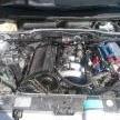
Goce Posted June 13, 2016 Author Report Share Posted June 13, 2016 Today i got tired at looking at the mess next to the car so i started cleaning it, after awhile i got bored and finished cleaning the lobro joints and axles, one is ruined and i do not plan to use it. The other one is like new, after that i offered up the throttle body and is close to the radiator, i was planning to order silicone reducer, and by the look i would have made a mistake, now i'm waiting on couple of parts to start making the engine mounts. Quote Link to comment Share on other sites More sharing options...
Goce Posted June 14, 2016 Author Report Share Posted June 14, 2016 I've been waiting on a couple of pieces of thick square and round steel, my steel yard have tubing in stock but thick steel only by order. I want to use the stock engine mounts to hang the engine, and use two more as roll stoppers on the new frame rails, so wanting to make it nice and sturdy i've ordered some steel. I remember seeing a Costume made mounts on a Lada samara Diesel, thy never came with a diesel engine from the factory, they ware converted i france and use peugeot tud5 engine, so a found one, her engine mounts they are made out of steel, but o man are thay badly made, on first look the mount bang is nicely machined and the bolt bungs are nice but the part in between is horrible, there are pieces of rebar and a long bolt use in it., and some one bought the car new like that and lasted for 820,000km, that was the number on the speedo. I plan to use this gearbox mount from peugeot MA4 box that are steel instead of aluminium like the stock 405 wich means i can cut and weld it easy.The front zinc plated crossmember seems to heavy to use it there, i may cut it and use it on the roll stoppers, fun times. Quote Link to comment Share on other sites More sharing options...
Goce Posted June 14, 2016 Author Report Share Posted June 14, 2016 Today i put in a full day of work on the mi16, i spend almost 2 hours, centering the engine and box in the chassis, i center it and lifted it 15mm higher, so when the weight presses down it shud be in the right place. Decided to start on the passenger side engine mount first, started by mounting the exhaust manifold, coolant flange, so i could avoid them, then cut the top mount from the lada mount, that gives me a finishing point, then made 3 bongs, and bolted them to the block, then made a 7mm plate to connect them, that gives me a final point, after that i drill two holes in the new subframe for one more engine mount, is going to be more to stop the engine from rolling under load, than i used two pieces of pipe to connect the dots, after that i weld it fully, and put in couple of straightening plates, at the end i got tired and did not took photos when i finish, tomorrow i'll ground it smooth, and prime it , more to come. Quote Link to comment Share on other sites More sharing options...
Goce Posted June 15, 2016 Author Report Share Posted June 15, 2016 Today i started where i left yesterday, started by grounding the engine mount smooth, then i test fitted it and is sturdy, then i clean up and weld the subframe where i could, when the engine is out i'll finish welding. To start making the drivers side mount i need to fit the power steering pump and alternator, that means that i need to make new mounts for them, first thing i need to change is the engine pulley, but someone has over tighten the bolt, started with the impact gun and broke the socket, then tried with a wrench and a hammer, broke that wrench, then grabbed the pulley with big set of pliers to stop ti spinning, and a good big wrench, and a 2m pipe, and started jumping on it with my 110 kg and it let go, now i can't get the pulley of, tried using a standard 3 leg puller and broke the pulley, now i have to make a special puller, that is for tomorrow. Quote Link to comment Share on other sites More sharing options...
Goce Posted June 16, 2016 Author Report Share Posted June 16, 2016 Today i've been spending money on parts like crazy, i needed one more lobro joint, and when i need a specific part it seams price go up, i got this axle for 3 times the price more than the booth others, and i bought this big piece of 32mm c 45 hss steel, i needed two 90 degrees bends, i had to contract a building company to bend it, thay said it was vary hard to bend, i was surprised how nice it come out, that also was expensive. Quote Link to comment Share on other sites More sharing options...
Goce Posted June 18, 2016 Author Report Share Posted June 18, 2016 Today i started where i left off,with an unbolted the center bolt on the front pulley it will not pull of, had to make a special puller, you can see i broke the pulley with a standard 3 arm puller, also you can see where i weld it last time it broke, i've replaced it 3 times, and i'm tired dealing with it that's why i'm doing this. And just as was pulling it i notice the center flange is cast together with timing belt sprocket so i can't use the pulley i planned to use, so new plan i'll try to use this pulley from a renault coupe i stripped for parts, i may use all the accessories from it, next thing i started with the mounting plate for the engine mount and i may use it to hang the alternator on it, i need to enlarge two holes, to make it fit, also bought couple more pieces of steel, for the engine mounts. Quote Link to comment Share on other sites More sharing options...
Bean Posted June 18, 2016 Report Share Posted June 18, 2016 One point about using the half shafts for the drive shaft: They spin much 3-4 times faster as the input shaft to the diff than they do on the output. My friend did the same on his locost and the boots kept exploding - turned out the increased shaft speed flung the grease into the boot and the centrifugal force from the higher shaft speed was too much. After multiple boot replacements he figured out the issue and lightly greased them instead. Caveat to this is that was for his track toy Locost/Super 7 that was bike powered (CBR900RR) with 100HP shot of NOS, and it weighed less than 1000lbs. It worked ok in that car, but heavier and longer loads would be a concern. Something to be aware of at least. Rabin Quote Link to comment Share on other sites More sharing options...
Goce Posted June 18, 2016 Author Report Share Posted June 18, 2016 Thank you for the advice, i'm considering installing a drive shaft hoop just in case it breaks. Quote Link to comment Share on other sites More sharing options...
Goce Posted June 20, 2016 Author Report Share Posted June 20, 2016 This work , i've done in the past couple of days, i've been busy and have not posted them. First i've disabled the last axle i've got and clean the lobro joint, i also cut the axle thinking i may use the bigger part as a sleeve over the welded axle but the inside is to wide, so i found one that fits better, now only 6 more bolts and i'll have everything to complete the driveline, next thing i did was to enlarge the bolt holes for the flange on the drivers side engine mount, once it was fitting right, i started planning the brackets for the accessories, i got out all the brackets i had for peugeot i could not use any, so decided to cut the flange of one which has a bolt hole, offered up and mark'd where it lines up with the crank pulley, then drilled and tap it for m8, bolt it and then welded with some nickel electrodes, the flange is cast iron, then mounted the alternator and offered the power steering pump just to be in place to avoid them with the engine mount, than planned and at first it seem invisible to connect the flanges, after many failed attempts, i had to roll a tube to avoid the intake manifold, tack welded in place, next i started on the flange for the one extra mount, it bolts on the bolts for the A/C compressor, then got them out and welded solid, then started on the gearbox mount, started with the original mount that came with gearbox, is too low, straight piece is still low, so i added one more piece and drilled holes so i can access to bolt then, i'll probably add one more piece to connect frame rails more to come. Quote Link to comment Share on other sites More sharing options...
Goce Posted June 21, 2016 Author Report Share Posted June 21, 2016 I'm planning to use shock tower bar on my build, i like to tie them together main reason i've cut a lot of strength from that part, and by adding power it will twist it, my question is should i get an adjustable bar and should i pre load it and how much for the 405. Quote Link to comment Share on other sites More sharing options...
Goce Posted June 22, 2016 Author Report Share Posted June 22, 2016 Couple more parts arrived, one of which a T3 oil feed flange with a bigger hole, 1mm seems too small, new one is 4,5 mm, i'll use it, if the oil pressure drops too low, then i will run the restrictor one. Quote Link to comment Share on other sites More sharing options...
Goce Posted June 22, 2016 Author Report Share Posted June 22, 2016 I want to run a strut tower bar, i like the look of the aftermarket parts, but i love my oem parts, they are more affordable and regularly available, this one is from a renault megane coupe, it was 85mm short, so i got a m20 alen bolt and two nuts, i cut out the plastic retainer, and the bar perfectly matches on the inside, and i weld them, it is pretty thick piece of pipe and it weld very well, little paint and is finish. Quote Link to comment Share on other sites More sharing options...
Goce Posted June 22, 2016 Author Report Share Posted June 22, 2016 Today i finish a big part of the conversion, the engine is been held on its mounts, yesterday i finished the drivers side mount and started on the gearbox mount, i'm particularly proud with the gearbox mount, it is made of 7 pieces of steel, fully welded, and i bottled it with 6 bolt, couple tru the floor pan with spreader bars, and the others straight in the chassis, letter i will take it out to smooth it and protect it, couple more big puzzles to solve and the finishing work. Quote Link to comment Share on other sites More sharing options...
Goce Posted June 23, 2016 Author Report Share Posted June 23, 2016 One of the big puzzle to solve is the steering, so last night i called a friend and ask to use his workshop, hi has more equipment and tools, so i drill and threaded for the tie rod end extenders, the c45 is quite hard to drill and tap, they should work out fine, tomorrow i will tighten everything i also need to cut a taper in the spindle and i need check for rubbing on the full travel of the suspension, it seems that this projects is taking a long time, the shelf with all the parts from this project is sagging of the weight, more to come. Quote Link to comment Share on other sites More sharing options...
Goce Posted June 25, 2016 Author Report Share Posted June 25, 2016 I apologise to all who follow this build, i've been busy and i haven't made no progress i have to do a lot reorganizing of parts in the garage so i can find some parts that i need to continue, more to come. Quote Link to comment Share on other sites More sharing options...
Bean Posted June 25, 2016 Report Share Posted June 25, 2016 No need to apologize at all! Progress has been unrelenting and I'm amazed at your progress so far has been so fast. Rabin Quote Link to comment Share on other sites More sharing options...
Goce Posted June 27, 2016 Author Report Share Posted June 27, 2016 Last couple of days i've been organizing the garage, to be able to found all the sway bars that i have, i had 14 of them, couple are too long hitting the tires, started with the original one there was no space to install it towards the cabin, because it hits the steering rack, flip it towards the front and the tire hits it, then after couple more those in the picture where they came closest to fitting, the thickest was going to lay way to low, the one on the floor seams to be the right it is thinner at 20 mm, but the ends are longer and should apply more force, and the front end should be lighter as the box is in the middle, and by the looks i will have to run one more front crossmember to be able to bolt the sway bars on. Not too much progress but now the garage is clean i should be able to work more effectively, more to come. Quote Link to comment Share on other sites More sharing options...
Bean Posted June 27, 2016 Report Share Posted June 27, 2016 The longer the arms the weaker the roll moment will be - think of them as levers. The longer the lever the easier it is to twist the bar. Shorter and thicker will resist motion more. Anti-roll bar stiffness is also dependent on the total length of the bar - very similar to springs. Rabin Quote Link to comment Share on other sites More sharing options...
Goce Posted June 27, 2016 Author Report Share Posted June 27, 2016 37 minutes ago, Bean said: The longer the arms the weaker the roll moment will be - think of them as levers. The longer the lever the easier it is to twist the bar. Shorter and thicker will resist motion more. Anti-roll bar stiffness is also dependent on the total length of the bar - very similar to springs. Rabin I'm not that familiar with all the suspensions geometry, but the longer the lever the easier it is to twist the bar makes sense, do you have any advice what to look for at the breakers yard, distance between the bolts on the lower arms is 107sm on full droop and 110sm ride height 22 mm stok, can i simply drill new holes in the original sway bar, is there some point where the sway bar becomes too hard or negatively affects handling? Quote Link to comment Share on other sites More sharing options...

Recommended Posts
Join the conversation
You can post now and register later. If you have an account, sign in now to post with your account.